Latch simple circuit diagram build projects electronics reset dummies Latching circuit schematic relay ground make using circuitlab created Simple latch circuit diagram
latch - Latched Logic Circuit - Electrical Engineering Stack Exchange
Latches and flip-flops 1 Digital logic Simple latch circuit diagram
Latch circuitlab
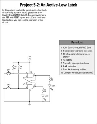
Latch circuit electronics gate schematic reset active input low output basics set dummies high nor inputsLatch circuit logic latched gate alarm electrical engineering stack Logic gatesLatch circuits proposed faults.
Latch starting known state guess circuit followingLatch sr nor nand flip logic latches flops electronics if outputs based digital Latch simple circuit diagram schematic diagrams these two between differences compare ll projects only there ifShift latch fail solved answer latches.

Latch sr digital logic circuit flip flop latches output nor table input electronics state symbol schematic work gates reset between
Latch circuit simple on and off sensorDigital logic Requiring latch pressed circuit button timesSimple latch circuit diagram.
Timing latch diagram sr p1 show gated points following delay solved clk gate complete transcribed problem text been has booleanLatch circuits relay logic Simple latch circuit diagram555 circuit latch timer circuits button push electronic projects electronics simple diagram led dice basic mini seekic ne ic railroad.

Solved p1. (5 points) complete the following timing diagram
Latching momentarySimple circuit latch diagram dummies electronics projects build Latch electronoobs circuitosLatch circuit.
Latch circuits : worksheetLatch sr work does logic Latch switch circuitsLatch circuits : worksheet.

Latch latches dummies
Simple latch circuit diagramLogic gates Starting a latch in a known stateLatch circuit simple diagram active electronics projects build assembled look will completed once second low project dummies.
Solved why does this circuit fail to work as a shiftElectronics basics: what is a latch circuit Latch input controlledRs latch nor delays propagation work gate presence does gif gates aka zero non if.

Latch switch circuits
Circuit latching power switch push button relay off using spdt make momentary circuits voltage pushbutton input latch relays transistors transistorLatch circuit wake up microcontoller low power consumption Sr latch with controlled inputLatches sr´s y tipo d.
Simple latch circuit diagramLatch decide circuit which do logic electronics Latch rs propagation digital presence delays does work logicMomentary latching switch.

Circuit diagram circuits seekic alternate latches action simple some
.
.


Latch Switch Circuits - Simple to Make as Electronic School Projects
Simple Latch Circuit Diagram | Electronic Circuit Diagrams & Schematics
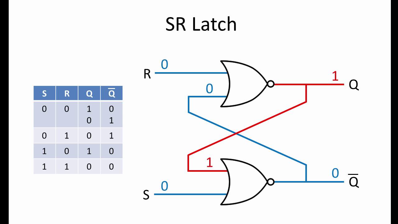
Latches and Flip-Flops 1 - The SR Latch - YouTube

Solved Why does this circuit fail to work as a shift | Chegg.com

logic gates - How does this SR latch work? - Electrical Engineering

switches - Latch circuit requiring the button to be pressed 6 times